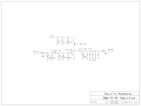
The original diagram was taken from the data sheet of Mitsubishi 2SC1946A designed to operate at 175MHz. Both input and output tuning network was modified to work between 88 to 108MHz very well intended for our main purpose. Large heat sink is required since the 2SC1946A must operate at 100% duty cycle. Forced air cooling aids in dissipating the heat produced by the rf transistor. The use of high voltage trimmer capacitor is a must and the use of ground plane technique is best suited for this project. RF input of 1 to 2 watts coming out from the exciter is enough to drive this amplifier to produce 20 to 25 watts of rf output assuming that the DC supply is at 12 volts. Take note that this rf amplifier is operated in class C therefore, the need for low pass filter in the output must be installed to avoid interference caused by the harmonics generated by this amplifier. --- 73 de hevir
Wednesday, July 20, 2011
Homebrew 30W FM Broadcast Amplifier
The original diagram was taken from the data sheet of Mitsubishi 2SC1946A designed to operate at 175MHz. Both input and output tuning network was modified to work between 88 to 108MHz very well intended for our main purpose. Large heat sink is required since the 2SC1946A must operate at 100% duty cycle. Forced air cooling aids in dissipating the heat produced by the rf transistor. The use of high voltage trimmer capacitor is a must and the use of ground plane technique is best suited for this project. RF input of 1 to 2 watts coming out from the exciter is enough to drive this amplifier to produce 20 to 25 watts of rf output assuming that the DC supply is at 12 volts. Take note that this rf amplifier is operated in class C therefore, the need for low pass filter in the output must be installed to avoid interference caused by the harmonics generated by this amplifier. --- 73 de hevir


