Monday, October 16, 2023

DIY 30W Power meter using 10dB Attenuator


While browsing the internet I came across a 100W/10dB attenuator resistor with a surprisingly low price. This sparked an idea in my mind - I could potentially use this affordable attenuators as a dummy load. What's more, I could connect a diode across its output to make a simple power meter.


The attenuator serves two purposes. 

1. It could function as dummy load as long as you terminate the output terminal with a 50 ohm load.
2. The rf detector is not subjected to extreme rf power as it is connected after the attenuator output.

Given the above details, I started the project as soon as the parts arrived. I had plenty of 180W/2W resistors in my junk box so I created a dummy load using them. According to my calculations, for a 30W of rf input, the 10dB / 100W resistor should effectively reduce it to approximately 3W and my 4 pieces of 180 ohm/2W resistors can safely dissipate the remaining 3W of power.


1N4148 diode is connected across the attenuator output to sample the amount of power being dissipated by the dummy load resistors. A sensitive 200uA ammeter is used to display the power measurement.


I calibrated my DIY power meter using Diamond SX200 swr/power meter as a reference. During the initial test, it exhibited a broadband characteristic. I conducted measurement validation across a range from 88MHz until 173MHz and observed a pleasant flat response. ---73 de du1vss

Monday, September 11, 2023

Advantech WISE-4220-S231 IoT Wireless Module


Today, I will be sharing the advantages of using IoT devices such as the Advantech WISE-4220-S231 wireless sensor. The  WISE 4220 series is an Ethernet-based wireless  IoT device.  What makes this device particularly useful is that its I/0 module is removable and can be replaced with other variants for different applications. Below are the listing of available I/O module for the WISE-4220 series
  1. S231 - built-in temperature and humidity sensors.
  2. S214 - 4 analog inputs and 4 digital inputs.
  3. S250 - 6 digital inputs, 2 digital outputs and 1 rs-485 input.
  4. S251 - 6 digital inputs and 1 rs-485 input.


What we have on-hand is the WISE-4220 with S231 variant. Powering the module is simple. It accepts voltages ranging from 10Vdc to 50Vdc. How convenient is that right? Just wait for a few seconds after powering the module and it will start broadcasting its SSID and ready to accepts WiFi connections. You can use your own cellphone or pc to access the wireless web interface. WISE-4220 can be also configured to connect over a wireless network. Data transmission uses the industry standard TCP Modbus protocol. Accessing the module anywhere is much easier as long as you are within the same network.


---73 de du1vss

Tuesday, June 20, 2023

DIY Arduino Uno Data Logger


Another great project that you can make with arduino is the datalogger. The basic design of a logger calls for a timer, a memory and converter that will translate analog signals from the sensor into a digital data. Today, all of these components are readily available and cheap too. So here are the things you need.

1. Arduino Uno microcontroller.
    

2. 16 x 2 LCD module.


3. DS1307 RTC module.

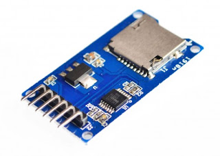
4. MicroSD Card module.


Start connecting the modules to the arduino by following the picture below. Take note that LCD module is not included in the wiring diagram.


DA1307 RTC module also uses the A4 and A5 pins of the Arduino for its SCL and SDA line. This leaves A0, A1, A2 and A3 as your remaining analog inputs. Never the less, it is still sufficient for this project.


Above is the picture of my completed datalogger. Sampling time is set every 5 minutes. The LCD displays the current time and data but during a short sampling period, it will display **** to tell the user that analog signals at A0, A1, A2 and A3 has been sampled and logged into the sd card successfully.

Below is the code I wrote for my arduino datalogger.

/////////////////////////////////////////////////////////////////////////////////////////////////////////////////////////////////////////////

#include <uRTCLib.h>
#include <LiquidCrystal.h>
#include <SPI.h>
#include <SD.h>

File myFile;
uRTCLib rtc;

const int rs = 9, en = 8, d4 = 5, d5 = 4, d6 = 3, d7 = 2;
LiquidCrystal lcd(rs, en, d4, d5, d6, d7);


void setup() {
delay (2000);

lcd.begin(16, 2);  //initialize LCD module.


if (!SD.begin(10))   //initialize SD module. Chipselect is 10
{
  lcd.clear();
  lcd.setCursor(0,0);
  lcd.print("SD Init Failed");
  while(1);
}

lcd.print("SD Init Done");
delay(1000);


  #ifdef ARDUINO_ARCH_ESP8266
    URTCLIB_WIRE.begin(0, 2); // D3 and D4 on ESP8266
  #else
    URTCLIB_WIRE.begin();
  #endif


  rtc.set_rtc_address(0x68);

  // Only used once, then disabled
  //  rtc.set(0, 42, 16, 6, 2, 5, 15);
  //  RTCLib::set(byte second, byte minute, byte hour, byte dayOfWeek,
// byte dayOfMonth, byte month, byte year)

  //rtc.set(0, 19, 12, 6, 3, 6, 23);
 
}

void loop()

{
  rtc.refresh();
  lcd.clear();
 

  lcd.setCursor(0, 0);


  lcd.print(rtc.month());
  lcd.print('/');
  lcd.print(rtc.day());
  lcd.print('/');
  lcd.print(rtc.year());


  lcd.print(' ');
 

  lcd.print(rtc.hour());
  lcd.print(':');
  lcd.print(rtc.minute());
  lcd.print(':');
  lcd.print(rtc.second());
 
  lcd.setCursor(0, 1);
//  lcd.print("DOW: ");
//  lcd.print(rtc.dayOfWeek());

if  (rtc.dayOfWeek() == 1)
{lcd.print("Monday");}

if (rtc.dayOfWeek() == 2)
{lcd.print("Tuesday");}

if (rtc.dayOfWeek() == 3)
{lcd.print("Wednesday");}

if (rtc.dayOfWeek() == 4)
{lcd.print("Thursday");}

if (rtc.dayOfWeek() == 5)
{lcd.print("Friday");}

if (rtc.dayOfWeek() == 6)
{lcd.print("Saturday");}

else if (rtc.dayOfWeek() == 7)
{lcd.print("Sunday");}

  delay(1000);

  ////////////Code for data logger begins here....

  int x = (rtc.minute() % 5); /// minute value is divided by 5,
/// the remainder is stored
                               /// in integer x.

  if (x + rtc.second() == 0)  /// Sampling of the logger.
{

  float voltA0 = (analogRead(A0) * (5.0 / 1023.0));
  float voltA1 = (analogRead(A1) * (5.0 / 1023.0));
  float voltA2 = (analogRead(A2) * (5.0 / 1023.0));
  float voltA3 = (analogRead(A3) * (5.0 / 1023.0));


  myFile = SD.open("Logs.csv", FILE_WRITE);
 
  myFile.print(rtc.month());
  myFile.print('/');
  myFile.print(rtc.day());
  myFile.print('/');
  myFile.print(rtc.year());
  myFile.print(",");
  myFile.print(rtc.hour());
  myFile.print(":");
  myFile.print(rtc.minute());
  myFile.print(",");
  myFile.print(" ");
  myFile.print(" ");
  myFile.print(" ");
  myFile.print(" ");  
  myFile.print(voltA0);
  myFile.print(",");
  myFile.print(voltA1);
  myFile.print(",");
  myFile.print(voltA2);
  myFile.print(",");
  myFile.print(voltA3);
  myFile.println(" ");
 

  myFile.close();

  lcd.setCursor(12, 1);
  lcd.print("XXXX"); ///Prints XXXXXX in the lcd after
  delay(200);        ///recording all the analog channels.
}

else
{
 

}

}


---73 de du1vss