Saturday, November 9, 2013

Two Stack Dipole Using Power Divider


My friend ask me If I can make a two stack dipole for his 92.9MHz FM station and I decided to construct this project using a home made coaxial power divider using a two piece quarter-wave long 75 ohm coaxial cable. The two 75 ohm coax was connected in parallel to obtain 37.5 ohm which is the required impedance for our power divider. I also use a 1 wavelength long 50 ohm coax feeding the two dipoles and along with it, a short piece of wire that act as a pawsey stub that makes the dipole feed point balance. The 1 wavelength long 50 ohm coax was also chosen so that each dipole can be vertically spaced at 1 wavelength for gain optimization.


A plastic element insulator hold the dipole segments on a 1"x1" square tube boom. The feed point connection was carefully protected with a layer of rubber tape and on top of it is an electrical tape for UV and water protection.

A  fabricated  bracket  will hold the antenna boom and this was made of a thick plastic material, the one used here was a chopping board 5mm in thick.


A close up view of the coaxial power divider during initial tuning and testing.


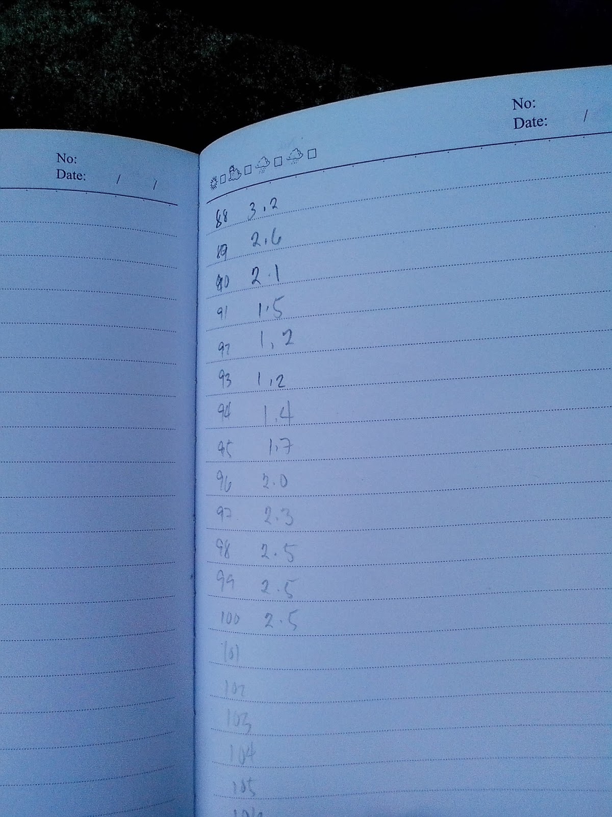
A quick frequency sweep was made to evaluate the antenna SWR after the trimming of dipole segments. The antenna bandwidth was quite narrow for this design and I was able to obtain an SWR value of 1:1.2 across 92MHz to 93MHz only.


During testing, the two dipoles were spaced 1 wavelength horizontally and was 1 meter above the ground  just only to evaluate the SWR and tune the antenna while at the ground. When installed permanently, this antenna is expected to yield  3dBd of gain theoretically.    73 de du1vss

Saturday, July 6, 2013

Switch Mode Power Supply Unstable Output Cure


I got this switch mode power supply from a friend and my plan was to use this on my 80W linear amp. Things went the other way when I tested this supply with my 80W amp. The output voltage won't stay at 12V and every time i keyed my transceiver, the output voltage swings to 15V and sometimes the worst hitting a peak at 17V which by any moment will surely blow the PA transistor of my amp. It took me a quite a while to figure out what was causing the issue but then it was the stray RF reaching the PWM switching regulator IC was the main culprit. My verification includes bringing a 6W portable hand held transceiver close to the switch mode power supply and pressing the PTT while monitoring the output voltage of the power supply. Every time i pressed the PTT the output voltage jumps to 17V  and the proximity of the rubber ducky antenna is directly proportional to the increased in output voltage of the power supply.


I got the courage to disassemble the switch mode power supply to access the circuit board and found the only chip mounted on the board. It was a AZ7500E pulse width modulator regulator chip that runs this power supply and found some important pins that are responsible for its regulation. I tried to bypass to ground pin1 and pin16 (both were (+) inputs of its built-in error amplifier) using a 0.01uF ceramic capacitor. After the modification I quickly reassembled the power supply and test again for stability and surprisingly works now normally. --- 73 de du1vss

Home Brew 60W RF Dummy Load

Another great way of making your own 60 watts dummy load is by the use of Caddock thick film power resistor.  Purchased some of these at http://philippines.rs-online.com/web/ which cost  at 270 Pesos each. Two 100 ohm / 30W resistors were paralleled to make a 50 ohm / 60W dummy load. The good thing about this product is that it comes in TO-220 package and mounting this on a suitable aluminum heat sink is a big help in heat dissipation during actual use. Been able to test my prototype on VHF and provides a very good matched at 144MHz exhibiting an SWR value of 1.1:1 across the amateur band due to the fact that reactive components can be easily minimized because of the unique package of this resistor.


Thermal compound was added between the aluminum surface in contact with the power resistors. A pig tail coax to PL259 connection was also included but a slight increase in SWR was noted. 73 de du1vss

Saturday, June 15, 2013

Jpole Antenna with a Twist


Here is my own version of my Jpole antenna used in my ham station. Only the half wave radiator was exposed while the remaining quarter wave stub was kept inside on pvc pipe. The pvc pipe prevents rain water from entering the feed point that might affect the vswr of the antenna when raining. It also provides the required structure for our Jpole since this type of antenna works best if kept insulated from the tower.
The half wave radiator is made of 3/8" anodized aluminum tubing while the pvc pipe diameter is 1 &1/4". Marine epoxy was used to secure the half wave radiator into the center of the pvc coupling.


Several patches of (4" x 1") cartoon or thick cardboard used as spacer in the stub. Keep in mind that the 1 inch spacing of the stub is critical since the stub is actually a ladder line but only shorted at the bottom. Finding the exact position of the feed point is done by trial and error and of course with the aid of your swr meter. After the actual tuning, I found my feed point to be at 0.05 wavelength from the bottom of the stub.The inclusion of the pawsey stub is only my personal preference to minimize feed line radiation but other methods can be used here.
Once completed, secure your Jpole antenna using a pair of scaffolding clamp on the top of your tower.   --- 73 de du1vss