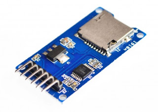
Another great project that you can make with arduino is the datalogger. The basic design of a logger calls for a timer, a memory and converter that will translate analog signals from the sensor into a digital data. Today, all of these components are readily available and cheap too. So here are the things you need.
1. Arduino Uno microcontroller.
2. 16 x 2 LCD module.
3. DS1307 RTC module.
Start connecting the modules to the arduino by following the picture below. Take note that LCD module is not included in the wiring diagram.
DA1307 RTC module also uses the A4 and A5 pins of the Arduino for its SCL and SDA line. This leaves A0, A1, A2 and A3 as your remaining analog inputs. Never the less, it is still sufficient for this project.
Above is the picture of my completed datalogger. Sampling time is set every 5 minutes. The LCD displays the current time and data but during a short sampling period, it will display **** to tell the user that analog signals at A0, A1, A2 and A3 has been sampled and logged into the sd card successfully.
Below is the code I wrote for my arduino datalogger.
/////////////////////////////////////////////////////////////////////////////////////////////////////////////////////////////////////////////
#include <uRTCLib.h>
#include <LiquidCrystal.h>
#include <SPI.h>
#include <SD.h>
File myFile;
uRTCLib rtc;
const int rs = 9, en = 8, d4 = 5, d5 = 4, d6 = 3, d7 = 2;
LiquidCrystal lcd(rs, en, d4, d5, d6, d7);
void setup() {
delay (2000);
lcd.begin(16, 2); //initialize LCD module.
if (!SD.begin(10)) //initialize SD module. Chipselect is 10
{
lcd.clear();
lcd.setCursor(0,0);
lcd.print("SD Init Failed");
while(1);
}
lcd.print("SD Init Done");
delay(1000);
#ifdef ARDUINO_ARCH_ESP8266
URTCLIB_WIRE.begin(0, 2); // D3 and D4 on ESP8266
#else
URTCLIB_WIRE.begin();
#endif
rtc.set_rtc_address(0x68);
// Only used once, then disabled
// rtc.set(0, 42, 16, 6, 2, 5, 15);
// RTCLib::set(byte second, byte minute, byte hour, byte dayOfWeek,
// byte dayOfMonth, byte month, byte year)
//rtc.set(0, 19, 12, 6, 3, 6, 23);
}
void loop()
{
rtc.refresh();
lcd.clear();
lcd.setCursor(0, 0);
lcd.print(rtc.month());
lcd.print('/');
lcd.print(rtc.day());
lcd.print('/');
lcd.print(rtc.year());
lcd.print(' ');
lcd.print(rtc.hour());
lcd.print(':');
lcd.print(rtc.minute());
lcd.print(':');
lcd.print(rtc.second());
lcd.setCursor(0, 1);
// lcd.print("DOW: ");
// lcd.print(rtc.dayOfWeek());
if (rtc.dayOfWeek() == 1)
{lcd.print("Monday");}
if (rtc.dayOfWeek() == 2)
{lcd.print("Tuesday");}
if (rtc.dayOfWeek() == 3)
{lcd.print("Wednesday");}
if (rtc.dayOfWeek() == 4)
{lcd.print("Thursday");}
if (rtc.dayOfWeek() == 5)
{lcd.print("Friday");}
if (rtc.dayOfWeek() == 6)
{lcd.print("Saturday");}
else if (rtc.dayOfWeek() == 7)
{lcd.print("Sunday");}
delay(1000);
////////////Code for data logger begins here....
int x = (rtc.minute() % 5); /// minute value is divided by 5,
/// the remainder is stored
/// in integer x.
if (x + rtc.second() == 0) /// Sampling of the logger.
{
float voltA0 = (analogRead(A0) * (5.0 / 1023.0));
float voltA1 = (analogRead(A1) * (5.0 / 1023.0));
float voltA2 = (analogRead(A2) * (5.0 / 1023.0));
float voltA3 = (analogRead(A3) * (5.0 / 1023.0));
myFile = SD.open("Logs.csv", FILE_WRITE);
myFile.print(rtc.month());
myFile.print('/');
myFile.print(rtc.day());
myFile.print('/');
myFile.print(rtc.year());
myFile.print(",");
myFile.print(rtc.hour());
myFile.print(":");
myFile.print(rtc.minute());
myFile.print(",");
myFile.print(" ");
myFile.print(" ");
myFile.print(" ");
myFile.print(" ");
myFile.print(voltA0);
myFile.print(",");
myFile.print(voltA1);
myFile.print(",");
myFile.print(voltA2);
myFile.print(",");
myFile.print(voltA3);
myFile.println(" ");
myFile.close();
lcd.setCursor(12, 1);
lcd.print("XXXX"); ///Prints XXXXXX in the lcd after
delay(200); ///recording all the analog channels.
}
else
{
}
}
---73 de du1vss


