Above photo is the hand drawn illustration of my own version of Turnstile antenna used for my fm broadcast test station. It is basically two dipoles feed using a 75 ohms phasing harness but intentionally one of the dipole is 90 degrees delayed from the other dipole in order to have a circular polarization. You may find my design differs from the usual turnstile antenna posted in the internet anyway, in my project the two open dipoles is known to have an input impedance of 75 ohms. Feeding the these dipoles using a 75 ohms phasing harness will not transform the impedance therefore two 75 ohms phasing line in parallel will yield 37.5 ohms. You may find the 37.5 ohms a little mismatch with our 50 ohms transmission line but this will just raise the standing wave ratio to 1.3 : 1 which i think not too bad for the transmitter. For those who would like a perfect match, you can include a matching transformer out of coaxial cable but be reminded for the additional loss it would create. To avoid feedline radiation, pawsey stub was installed to each dipole using a #16 stranded wire cut to a quarter wave length of the operating frequency. When computing the phasing harness, include the velocity factor for the coaxial cable used. The signal polarization of this antenna is circular and purposely chosen to minimize the multipath fading. The theoretical gain is only -3dBd reference to a vertical dipole therefore multiple stacking is recommended. ---73 de hevir
Monday, October 24, 2011
Wednesday, July 20, 2011
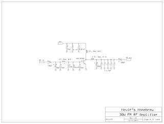
Homebrew 30W FM Broadcast Amplifier
The original diagram was taken from the data sheet of Mitsubishi 2SC1946A designed to operate at 175MHz. Both input and output tuning network was modified to work between 88 to 108MHz very well intended for our main purpose. Large heat sink is required since the 2SC1946A must operate at 100% duty cycle. Forced air cooling aids in dissipating the heat produced by the rf transistor. The use of high voltage trimmer capacitor is a must and the use of ground plane technique is best suited for this project. RF input of 1 to 2 watts coming out from the exciter is enough to drive this amplifier to produce 20 to 25 watts of rf output assuming that the DC supply is at 12 volts. Take note that this rf amplifier is operated in class C therefore, the need for low pass filter in the output must be installed to avoid interference caused by the harmonics generated by this amplifier. --- 73 de hevir
Monday, June 20, 2011
Collinear antenna for FM transmitter
This collinear antenna works perfectly after the installation. The antenna is basically two dipoles excited in-phase and theoritically exhibits 3 dB of gain when compared to a dipole. 3/8" aluminum tubing was used here but i suggest 1/2" will do the job even better. The quarterwave stub is made of #12awg stranded wire and is grounded at the center(null). When properly tune, this antenna should have SWR value of 1:1.1 to 1:1.2. 73 de hevir
Sunday, November 7, 2010
Amateur Radio Exam Result, October 2, 2010
Feels good to have a new ticket. I would like to give thanks to my fellow hams (DX1CW) who have provided me the reviewers that made possible for me to pass the Class A amateur exam. ---73 de DU1VSS
Friday, July 9, 2010
Automatic Battery Charger
Here is a simple battery charger circuit intended for 12 Volt gell-type battery. Current is limited by the 7805 regulator IC and the limiting resistor (62 ohms) to approximately 250 milliamperes, anyway most small sized gell-type battery capacities ranges from 2.5AH to 7.5AH so charging time should take several hours. When the battery is full, the regulator adjust its voltage output from 15 volts down to 5 volts automatically terminate the charging process. ---73 de hevir
Wednesday, June 16, 2010
OPC-478 Cloning Cable
Another evening project is this OPC-478 cloning cable for my Icom IC-2200H. Credit is given to Icom which the original circuit was taken and also to the cloning software (CS-2200H) used on this project. The prototype board supply was taken from the RS232 port of the computer while if this does not work, the 5 volts can be supplied externally. A quick check on the COM port setting of your PC before running the cloning program will prevent any conflict. If your PC does not have RS232, you can have an RS232-to-USB converter available in computer shops. ---73 de hevir
Thursday, May 20, 2010
Solid State Relay (SSR) using MOC3020
The circuit uses the MOC3020 optocoupler that drives the triac to switch 220V of AC volt to a load. We have this project after one of our incubator heater failed due to a faulty mechanical relay. The triac on this circuit can be directly mounted on a suitable heatsink without a need for an insulator. The original circuit was taken from the MOC3020 Motorola datasheet. ---73 de hevir
Subscribe to:
Comments (Atom)


