Saturday, August 25, 2012
40m Regenerative Receiver
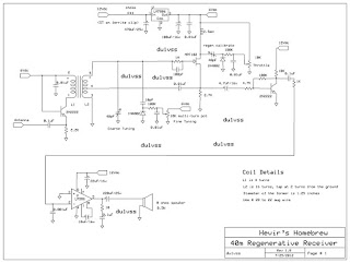
The first regenerative receiver was invented by Edwin Armstrong in 1914 and was been a standard receiver both for commercial and in amateur use long before the spread of super regenerative receiver. The circuit above was basically derived from the earlier works of Charles Kitchin, N1TEV and was modified for several improvements. Regenerative detectors able to detect nearly all types of signals including AM, CW, single-side band (SSB) and FM despite of its simplicity and fewer part counts. They tend also to consume less power, cost less and are easier to home brew than any other receiver.
The main modification of this project from the original design was the reduction of the variable air capacitor which due to the lack of availability of this item nowadays. It uses two tuning diodes (basically 1N4002 in reverse bias) to control the Fine Tuning and the other one is for the Throttle adjustment. A single transistor audio pre-amp was also included between the main input of the 386 main audio amplifier IC for added audio gain.
The tuning diodes provide a smooth adjustment of the Fine Tuning and of the Throttle control (regen). Stability isn't a problem at all.. small frequency drift may be noted on the first few minutes after power up which usually requires some warm up period. Once the receiver is up.. minor adjustment may be needed to clarify audio reception in single-side band (SSB).
This project was housed in a plastic casing but the original author suggested that wooden base may be used to avoid interaction with the air core transformer thereby reducing the "Q". First time user may require a little bit of control and manual adjustment specially the Throttle (regen). For AM reception, the detector must be adjusted just before oscillation and for CW, the regen may be moved a little over oscillation. When receiving SSB, the regen may be moved a little higher specially when receiving a stronger station to prevent frequency blocking.
The air core transformer contains the primary and secondary turns of # 22 magnetic wire. The core itself was made of 1.25" diameter of pvc pipe cut approximately 2" of length. Spacing of the primary turns to the secondary turns was about 1/4" but if you want some tight coupling a 1/8" spacing may be fine. The placement of the air core transformer is also important. Avoid placing the core in close proximity of metal objects such as speaker or transformer to avoid any unwanted effects. Placing the 12V power supply inside the receiver is not advisable since it will induce severe hum on the receiver's audio. The 12v wire going out to the external power supply must also be well filtered. I found out that 5 turns of the wire over a ferrite clip is already satisfactory. For my prototype receiver, a wire 10 meters in length acts a long wire antenna provides a sufficient reception of several DX stations heard in my area. Have fun with this project as I did. 73 de du1vss
Subscribe to:
Post Comments (Atom)


No comments:
Post a Comment