Monday, July 27, 2009

My 24Amps 13.8V Modified Regulated Power Supply


I just brought my new Steady-Volt 24Amps, 13.8Volts power supply
that cost several thousand bucks at RadioCom somewhere there in
Pasay. I was excited and at the same time curious on what is inside
of the unit. When I came home, I did not bother to check
the output voltage if it was correct but I did open the
unit to check the inside. To my surprise, there was not even one IC
present in the regulator board of the supply. Further checks revealed
that regulation was accomplished using an ordinary zener diode,
resistors,capacitors and few transistors. To my contentment, I tried
to trace their original circuit to find out how it works and the
results are:
1. Zener diode was used to provide regulation. It is known that
zener diode is not capable of sustaining good regulation
specially on higher current.
2. The power transistors were wired in series
pass configuration and is installed after the regulator. This design
flaw is the main reason why the supply could not maintain
regulation when the load draws high current.
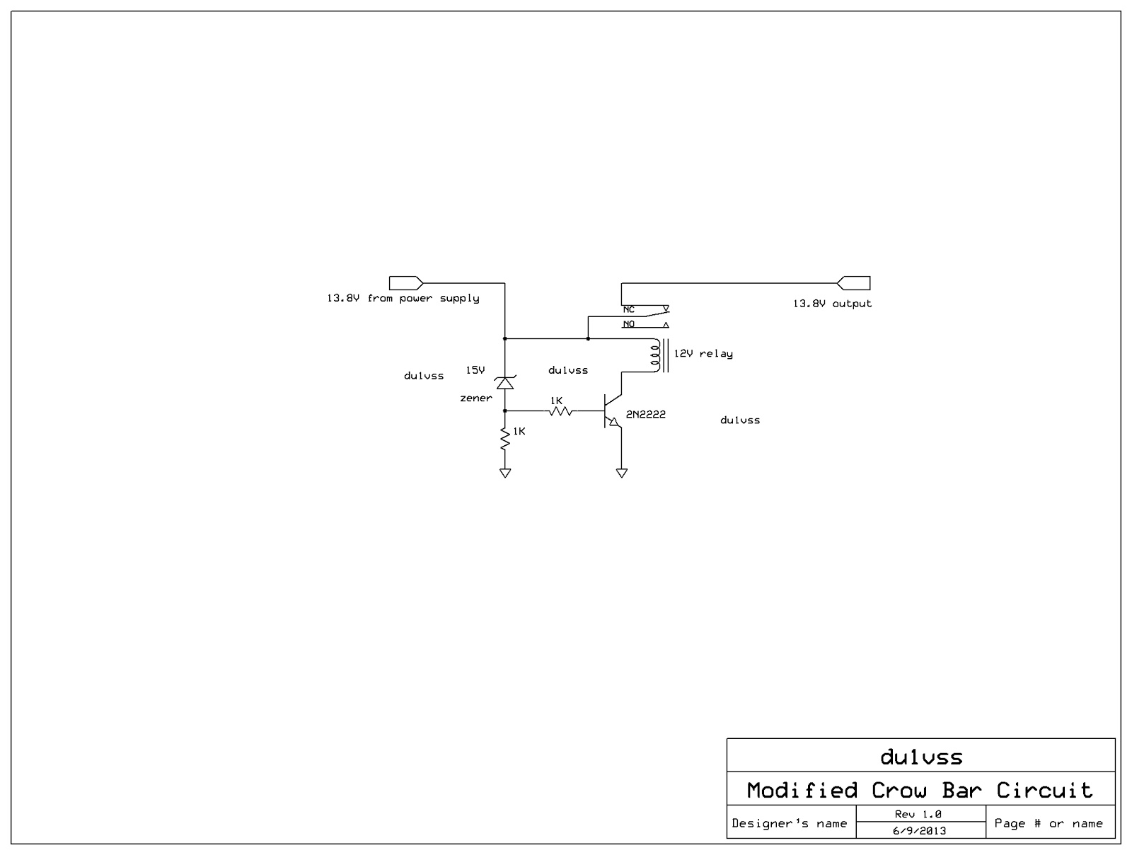
3. The OVP circuit (over voltage protect) is continuously on (relay)
while the power supply unit is idle. With this condition, the relay
coil might easily burned and will not sustain long hours of continuous
operation.
Several research on the internet leads me to the data sheet of LM317
from National Semiconductor which have the example applications of
their product. One example of LM317 circuit looks promising and can be easily
be replaced with a 7812 regulator to eliminate the use of biasing resistors.
The regulator circuit employs a PNP transistor that drive the bases of the
current hungry pass transistors. The 7812 regulator IC was wired as
wrap-around thus,it can able to maintain good regulation even if the load
draws more current. Prototype followed after I have secured all the
needed parts on the circuit. Final testing of the modified unit showed a
very stable output voltage at a varying load currents. My modified power
supply was able to power my IC-2200H at 65 watts and to the IC-720 HF
transceiver 100 watts on SSB.    ---73 de hevir

Monday, June 8, 2009

Homebrew your 4:1 Coaxial Balun


When the antenna has an input impedance of 300 ohms balanced line, the 4:1 coaxial balun easily transforms this to match with our 50 ohms unbalance transmission line. One example to this is the folded dipole whose input impedance is 300 ohms  and is balanced at its feed point.

To start with the construction, first we need to know the operating frequency of the balun. Assuming at 145MHz, so we may have the formula below.

Solve for the wavelength at 145MHz;

    wavelength (feet) = 984 / 145MHz
    wavelength (feet) = 6.78 ft.

We can express our unit of measurement by "inch" for ease in the calculation;
    
    wavelength (inches) = 81.43 inches

We need also to consider the velocity factor of the coaxial cable used which in this case for the RG-58 is 0.66 (dielectric is made of PE).

Solving for the actual physical wavelength;

    wavelength (inches) = 81.43 (0.66)
    wavelength (inches) = 53.75 inches

Solving for the required 1/2 wavelength;

    1/2 wavelength (inches) = 53.75 / 2
    1/2 wavelength (inches) = 26.87 inches

Given above formula, you can easily compute for the required length of the 1/2 wavelength at any operating frequency.   --- 73 de du1vss

Sunday, November 23, 2008

The VHF J-pole antenna


The J-pole antenna earned its name as one of the most popular VHF antenna because of its simplicity and its considerable gain when compared to any dipole or ground plane. Aside from its low angle radiation, the J-pole can be DC grounded which provides excellent protection from lightning overload that pose potential damage to the receiver.

The J-pole antenna evolved in may ways but its basic parts remained the same. The bottom portion is the quarterwave matching section wherein balance feeding can be connected. Connected above the quarterwave matching section is its radiator. The radiator can be cut 1/2 wavelength but if you want greater gain it can be cut to 5/8 wavelength without degrading the SWR at the feed point.

In my project, the bottom portion which is the quarterwave matching section and the lower 5/8 wave radiator is made of 1/2" OD anodized aluminum for added rigidity to sustain strong wind loads from storm. The upper 5/8 wave radiator is made of 3/8" OD anodized aluminum. The two radiator is connected via 3/8 wave phasing stub and is made of # 10 AWG solid electrical wire localy available at hardwares. The transmission line is coupled by 1:1 balun at the feed point of the antenna wherein minimum SWR is found. Once fully constructed, the j-pole exibits a theoritical gain of approximately 6 dB in reference to a standard dipole. --- 73 de hevir


Thursday, September 11, 2008

Regulated 15 Amps. Power Supply

This project is very simple to construct using cheap few components and easy circuit lay-out. Regulation of this project uses the fixed 3 terminal regulator 7815 as we know. You may noticed that 7815 will give an output of 15volts but because of the 3 amperes rectifier diode connected right after the output of the regulator, it drops the voltage down to 14.3volts furthermore the pass transistor used on this circuit are wired in series pass configuration, it adds another voltage drop down to 13.6volts which is pretty close to 13.8volts, anyway to beef-up the required current, two sets of 2N3771 NPN transistors capable of 30amps each connected in parallel and in series pass configuration. 

In the construction make sure that the heat sink is large enough to provide sufficient dissipation of the heat generated by the two power transistor.  Large diameter wire must be also used such #12 WAG stranded wire for the wiring of the circuit. If desired you can also add a small air blower to control the temperature of the power supply. ...73 de hevir

Thursday, August 21, 2008

3 Elements 2-Meter Yagi Antenna

This antenna project uses another approach in feeding the driven element. Instead of using gamma-feed dipole as its driven element, it uses a center feed dipole in combination of a 1:1 coaxial balun. This method of feeding a dipole eliminated the difficulty in tuning the driven element. The details of the coaxial balun was earlier discussed in my previous project. I build mine in less than 3 hours so this should be easy for most beginners. ---73 de hevir

Monday, August 4, 2008

Simple Over-Voltage Protection For Regulated Power Supply


This little protection circuit can be very useful in protecting your transceiver unit. I was able to design this circuit out from my horrible experience wherein my 30 Amps Zebra power supply unit suddenly went wild exploding my 90 watts Daiwa RF amplifier. Its too late but never the less, this project will help you a lot. The original circuit uses an SCR in conjunction with a fuse but later modified it using a much simplier approach using a 12V relay. Although the author is aware by the delay of closure brought by the relay contacts but actual test showed no problem with the radio transceiver during a simulated over voltage test at the power supply.---73 de hevir

Sunday, July 20, 2008

VOX Type PC to Radio Interface for Internet Link

The usual two meter radio communication is very limited when talking about coverage distance. This is due to the fact that at VHF frequencies and beyond, radio propagation is likely on line of sight. The higher your antenna is, the greater the distance it will cover. Nowadays technology has gone far; with the aid of internet communication thru VOIP, voice communication brings the world closer together. To cope with the advancement of technology, amateurs able to communicate worldwide thru their radios but not with the use of a huge and bulky HF transceivers, instead they were able to use the internet technology to hook up their radios to the internet. Available commercial interface unit cost so much that putting up a server is difficult.


This simple PC to radio interface project functions as a voice activated switch that will enable the audio from the radio to be retransmitted to the internet and vice versa with the use of a PC. The connecting wires must be a shielded type to avoid stray rf pick-up that might affect interface functionality. Internal power supply unit is needed especially when a portable transceiver is used while this can be eliminated if a mobile base transceiver is available since the 8 volts supply can be taken directly from the microphone input connector. The software for this project is the SKYPE because it can be downloaded for free on the internet. Implementations of this project can be a server, station identifier or to link several repeaters all over the world.  ---73 de hevir