Saturday, August 25, 2012

5Watts RF Amplifier for FM Broadcast


This project was realized for the need of boosting the rf signal of an ordinary FM modulator . Most of these FM modulators available on the market have an rf output of less than 5mW in which effective range was very limited. The circuit above contains several rf stages combined together in a 2"x 2" double sided PCB board. The two rf transistors namely 2N2222 and 2SC2053 do not need heat sink except for the 2SC1971 final rf transistor. There are two supplies required to operate this amplifier, the Vcontrol and the Vcc. The Vcontrol is designed to directly control the rf output of this amplifier therefore it should be adjustable from 6V to 12V. You may include a variable regulator like 317 but I have used the 7805 configured to be adjustable for the Vcontrol section. The Vcc is normally at 12V and at least 3 amperes. You can use 13.8V as well but be reminded that this will force the 2SC1971 to operate at a higher power output and will greatly increase the junction temperature and for safety reason 12V is recommended. Before tuning this amplifier, rotate all the trimmer capacitors to a 50% mesh position and set the Vcontrol at 11V. Set the FM modulator at the center of the broadcast band which in this case at 98MHz. Tuning process starts from the two trimmer capacitors found at the output section of the 2SC1971. Use a 50 Ohm dummy load together with a power meter and adjust these trimmers for a peak power then you may follow the other two trimmer capacitors located at the input section. Repeat this process few times until the rf output maximize. Double check the rf output at 88MHz and note the rf power, do the same at 108MHz.


The rf power output of this amplifier should give you a fair broadband characteristic and power level across the broadcast band should not drop too low. Note that you may reach 8W for the maximum power but this will put to much stress to our 2SC1971. You may now reduce the voltage at the Vcontrol to a lower value depending on your power level requirements.   ---73 de hevir

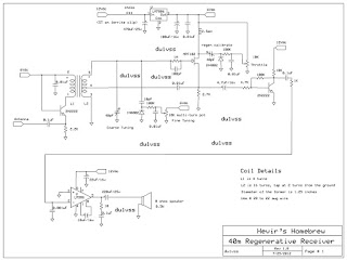
40m Regenerative Receiver


The first regenerative receiver was invented by Edwin Armstrong in 1914 and was been a standard receiver both for commercial and in amateur use long before the spread of super regenerative receiver. The circuit above was basically derived from the earlier works of Charles Kitchin, N1TEV and was modified for several improvements. Regenerative detectors able to detect nearly all types of signals including AM, CW, single-side band (SSB) and FM despite of its simplicity and fewer part counts. They tend also to consume less power, cost less and are easier to home brew than any other receiver.

The main modification of this project from the original design was the reduction of the variable air capacitor which due to the lack of availability of this item nowadays. It uses two tuning diodes (basically 1N4002 in reverse bias) to control the Fine Tuning and the other one is for the Throttle adjustment. A single transistor audio pre-amp was also included between the main input of the 386 main audio amplifier IC for added audio gain.


The tuning diodes provide a smooth adjustment of the Fine Tuning and of the Throttle control (regen). Stability isn't a problem at all.. small frequency drift may be noted on the first few minutes after power up which usually requires some warm up period. Once the receiver is up.. minor adjustment may be needed to clarify audio reception in single-side band (SSB).


This project was housed in a plastic casing but the original author suggested that wooden base may be used to avoid interaction with the air core transformer thereby reducing the "Q". First time user may require a little bit of control and manual adjustment specially the Throttle (regen). For AM reception, the detector must be adjusted just before oscillation and for CW, the regen may be moved a little over oscillation. When receiving SSB, the regen may be moved a little higher specially when receiving a stronger station to prevent frequency blocking.


The air core transformer contains the primary and secondary turns of # 22 magnetic wire. The core itself was made of 1.25" diameter of pvc pipe cut approximately 2" of length. Spacing of the primary turns to the secondary turns was about 1/4" but if you want some tight coupling a 1/8" spacing may be fine. The placement of the air core transformer is also important. Avoid placing the core in close proximity of metal objects such as speaker or transformer to avoid any unwanted effects. Placing the 12V power supply inside the receiver is not advisable since it will induce severe hum on the receiver's audio. The 12v wire going out to the external power supply must also be well filtered. I found out that 5 turns of the wire over a ferrite clip is already satisfactory. For my prototype receiver, a wire 10 meters in length acts a long wire antenna provides a sufficient reception of several DX stations heard in my area. Have fun with this project as I did. 73 de du1vss

Monday, April 23, 2012

Wilkinson Power Combiner / Splitter For VHF

This technology was first used in the FM broadcasting industry wherein most of the solid state rf amplifiers were combined to arrive a higher power levels.  The Wilkinson network is reversible that means that it can be used as a power divider to split power equally and it can be also used as a combiner. On this project, it uses a pair of Daiwa 80W rf booster (LA-2080) modified for "class C operation" and was only set at 70W output. Note that each rf amplifier should be identical so that there will be no phase difference on the signals arriving at the combiner network. For 144MHz, 4 pairs of RG-59 was used for the quarter wave section and several RG-58 cables for the patch cable used for connecting the radio transceiver to the Wilkinson input and from the Wilkinson output going to the power meter. Note that the RG-58 cables were cut at half wave of the operating frequency.

The 100 ohm resistor in the splitter section is rated 10W same also to the combiner section. During the test, the 100 ohm resistor at the combiner generates some heat and should have been increased in wattage to 50 or more for safety purposes. It is also necessary to match each amplifier and should have an equal rf output. This can be done by tuning each rf amplifier one at a time while keeping the other unit off. Please be aware that when one amplifier is off, the output power of the combiner is just a quarter of the original power output when all of the rf amplifiers are working together.  Once rf output of each rf amplifier are matched then the system is ready for use.


For the input drive of 5 watts I was able to measure 135W output from the combiner network. Please also observe the 100 ohm resistor at the combiner, too much heating means there is an imbalance between the two rf amplifier and should be equalize again.  ---73 de  du1vss

Saturday, October 29, 2011

Icom IC-2200H Adjustment Mode Jig


In order to adjust the power output of the IC-2200H transceiver it must come to "Adjustment Mode" and we need also the adjustment jig. The jig itself is made of 22K resistor connected to Pin7 and Pin2 of the RJ45 connector. When the jig is inserted to the microphone jack, "Adjustment Mode" can be initialized by holding the keys "SET" and "MONI" simultaneously while pressing "POWER ON"
The transceiver screen should look like this;


Adjustment items are displayed in the lower right corner of the LCD and these can be toggled by pressing the "BLANK OPT" or the "V/MHZ" keys. When the transceiver is on "Adjustment Mode" you can now remove the jig and reconnect the microphone. Please refer to the IC-2200H service manual for more details on the adjustment parameters. Note that the power output of the IC-2200H can be adjusted to 85W max by setting the PO parameter in the "Adjustment Mode". When done please perform a "Master Reset" to take effect the changes made on the transceiver.   ---73 de du1vss
Attachment: 2200H.pdf

Monday, October 24, 2011

Turnstile Antenna for FM Broadcast


Above photo is the hand drawn illustration of my own version of Turnstile antenna used for my fm broadcast test station. It is basically two dipoles feed using a 75 ohms phasing harness but intentionally one of the dipole is 90 degrees delayed from the other dipole in order to have a circular polarization. You may find my design differs from the usual turnstile antenna posted in the internet anyway, in my project the two open dipoles is known to have an input impedance of 75 ohms. Feeding the these dipoles using a 75 ohms phasing harness will not transform the impedance therefore two 75 ohms phasing line in parallel will yield 37.5 ohms. You may find the 37.5 ohms a little mismatch with our 50 ohms transmission line but this will just raise the standing wave ratio to 1.3 : 1 which i think not too bad for the transmitter. For those who would like a perfect match, you can include a matching transformer out of coaxial cable but be reminded for the additional loss it would create. To avoid feedline radiation, pawsey stub was installed to each dipole using a #16 stranded wire cut to a quarter wave length of the operating frequency. When computing the phasing harness, include the velocity factor for the coaxial cable used. The signal polarization of this antenna is circular and purposely chosen to minimize the multipath fading. The theoretical gain is only -3dBd reference to a vertical dipole therefore multiple stacking is recommended.   ---73 de hevir


Wednesday, July 20, 2011

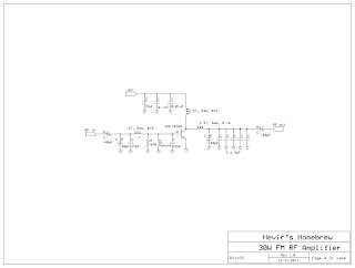
Homebrew 30W FM Broadcast Amplifier


The original diagram was taken from the data sheet of Mitsubishi 2SC1946A designed to operate at 175MHz. Both input and output tuning network was modified to work between 88 to 108MHz very well intended for our main purpose. Large heat sink is required since the 2SC1946A must operate at 100% duty cycle. Forced air cooling aids in dissipating the heat produced by the rf transistor. The use of high voltage trimmer capacitor is a must and the use of ground plane technique is best suited for this project. RF input of 1 to 2 watts coming out from the exciter is enough to drive this amplifier to produce 20 to 25 watts of rf output assuming that the DC supply is at 12 volts. Take note that this rf amplifier is operated in class C therefore, the need for low pass filter in the output must be installed to avoid interference caused by the harmonics generated by this amplifier. --- 73 de hevir

Monday, June 20, 2011

Collinear antenna for FM transmitter


This collinear antenna works perfectly after the installation. The antenna is basically two dipoles excited in-phase and theoritically exhibits 3 dB of gain when compared to a dipole. 3/8" aluminum tubing was used here but i suggest 1/2" will do the job even better. The quarterwave stub is made of #12awg stranded wire and is grounded at the center(null). When properly tune, this antenna should have SWR value of 1:1.1  to 1:1.2.   73 de hevir